A UART transmitter and receiver written in Verilog, verified in simulation with a self-checking testbench in Icarus Verilog. UART is the serial link on almost every microcontroller: one wire in each direction and no shared clock. This project was an exercise in RTL design, building a real protocol out of counters, shift registers and state machines, then testing it properly. Simulation only, not yet synthesised or run on an FPGA.
The link uses 8N1 framing: the line idles high, then each byte goes out as a low start bit, 8 data bits LSB first, and a high stop bit. With no clock shared between the two ends, the receiver has to work out the bit timing from the line itself.

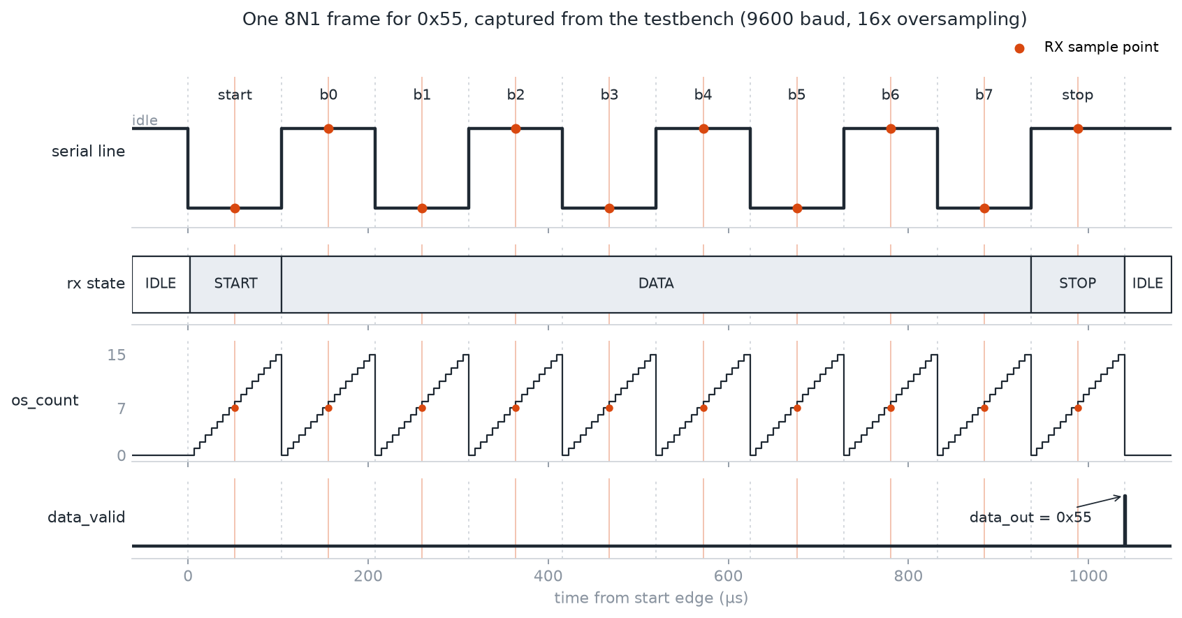
One frame for 0x55, plotted from the testbench’s waveform dump. The orange dots are where the receiver samples the line, at count 7 of its 0–15 oversample counter, right in the middle of each bit.
Modules
| Module | Notes |
|---|---|
baud_gen.v | Clock divider, parameterised on CLK_FREQ, BAUD_RATE and OVERSAMPLE. Outputs a one-cycle tick |
uart_tx.v | Four-state FSM (idle, start, data, stop). Shifts out one bit per tick, with busy and done outputs |
uart_rx.v | Four-state FSM with 16x oversampling. Outputs the byte with data_valid, or frame_error on a bad stop bit |
uart_tb.v | Self-checking loopback testbench |
Baud generator. A free-running counter that pulses baud_tick high for exactly one system clock cycle every CLK_FREQ / (BAUD_RATE × OVERSAMPLE) cycles. The same module drives both ends: the transmitter takes one tick per bit, and the receiver takes a second instance running 16 times faster.
localparam integer DIVISOR = CLK_FREQ / (BAUD_RATE * OVERSAMPLE);
Transmitter. A start pulse latches the byte into a shift register and raises busy. The FSM then waits for the next baud tick before pulling the line low for the start bit, so every bit lines up with the tick, and on each following tick shifts out the next bit LSB first:
tx        <= shift_reg[0];
shift_reg <= {1'b0, shift_reg[7:1]};
After the eighth bit it drives the stop bit high, drops busy and pulses done. Because the next byte also waits for a tick before its start bit, a new byte can be sent straight away and the stop bit still gets its full bit period.
How the receiver works
The serial input is asynchronous to the receiver’s clock, so it first passes through two flip-flops to stop metastability spreading into the logic. A third register keeps the previous value, so a falling edge (idle high to start-bit low) can be detected:
wire start_edge = rx_prev & ~rx_sync; // falling edge: idle(1) -> start(0)
From that edge, the receiver counts 16 oversample ticks per bit and does the same two things for every bit: sample the line at count 7, the middle of the bit, and move on to the next bit at count 15.
- Start bit: must still be low when sampled, otherwise it was a noise glitch and the receiver goes back to idle
- Data bits: sampled into a shift register, LSB first
- Stop bit: must be high, otherwise
frame_errorpulses instead ofdata_valid
The start-bit bug. The first version moved on from the start bit at count 7 instead of 15, straight after checking it. That made the start bit only half a bit long as far as the receiver was concerned, so every later sample landed half a bit early, right on the edges between bits, and bytes came out shifted or corrupted. Giving the start bit the same sample-at-7, advance-at-15 pattern as the other bits fixed it:
START: if (baud_tick_x16) begin
    if (os_count == 4'd7)
        start_ok <= ~rx_sync;

    if (os_count == 4'd15) begin
        os_count <= 4'd0;
        if (start_ok) begin
            bit_idx <= 3'd0;
            state   <= DATA;
        end else begin
            state <= IDLE;
        end
    end else begin
        os_count <= os_count + 1'b1;
    end
end
Testing
The testbench wires the transmitter’s output straight into the receiver’s input and checks every byte that comes out. The clock and baud rate were picked for fast simulation rather than real hardware: a 1.536MHz clock at 9600 baud gives an exact 160-cycle bit period and a 10-cycle oversample tick, where a real 50MHz board clock would take far more simulated cycles per byte for no extra coverage.
It runs two sets of tests:
- Single bytes: 8 bytes sent one at a time, waiting for each to arrive:
0x00and0xFF(all zeros, all ones),0xA5and0x5A(alternating),0x01and0x80(a single bit at either end),0x55(ASCIIU) and0x3C - Back-to-back burst: 5 bytes sent the moment the transmitter is free, without waiting for the receiver. Each new start bit lands at a different point relative to the receiver’s oversample counter, which tests exactly the kind of start-bit timing bug above
A byte fails if it arrives wrong, raises frame_error, or doesn’t arrive before a watchdog timeout, so a broken design fails quickly instead of hanging. A global timeout catches the simulation locking up completely. The run ends with:
Sent: 13  Received: 13  Errors: 0
RESULT: ALL TESTS PASSED
The testbench also dumps a VCD, which is where the timing diagram above comes from, and can be opened in GTKWave with make wave.
Limitations
Both ends of the loopback share one clock, so the testbench doesn’t cover a clock mismatch between transmitter and receiver, which is the main thing a real UART link has to tolerate. It’s also 8N1 only, with no parity bit and no buffering, so a byte has to be read before the next one arrives.
Next steps: an optional parity bit with a parity error flag, and running it on an FPGA with the transmitter wired to a USB-UART adapter, so bytes show up in a terminal on a PC.
Stack: Verilog, Icarus Verilog, GTKWave, Make
Status: complete (simulation only)