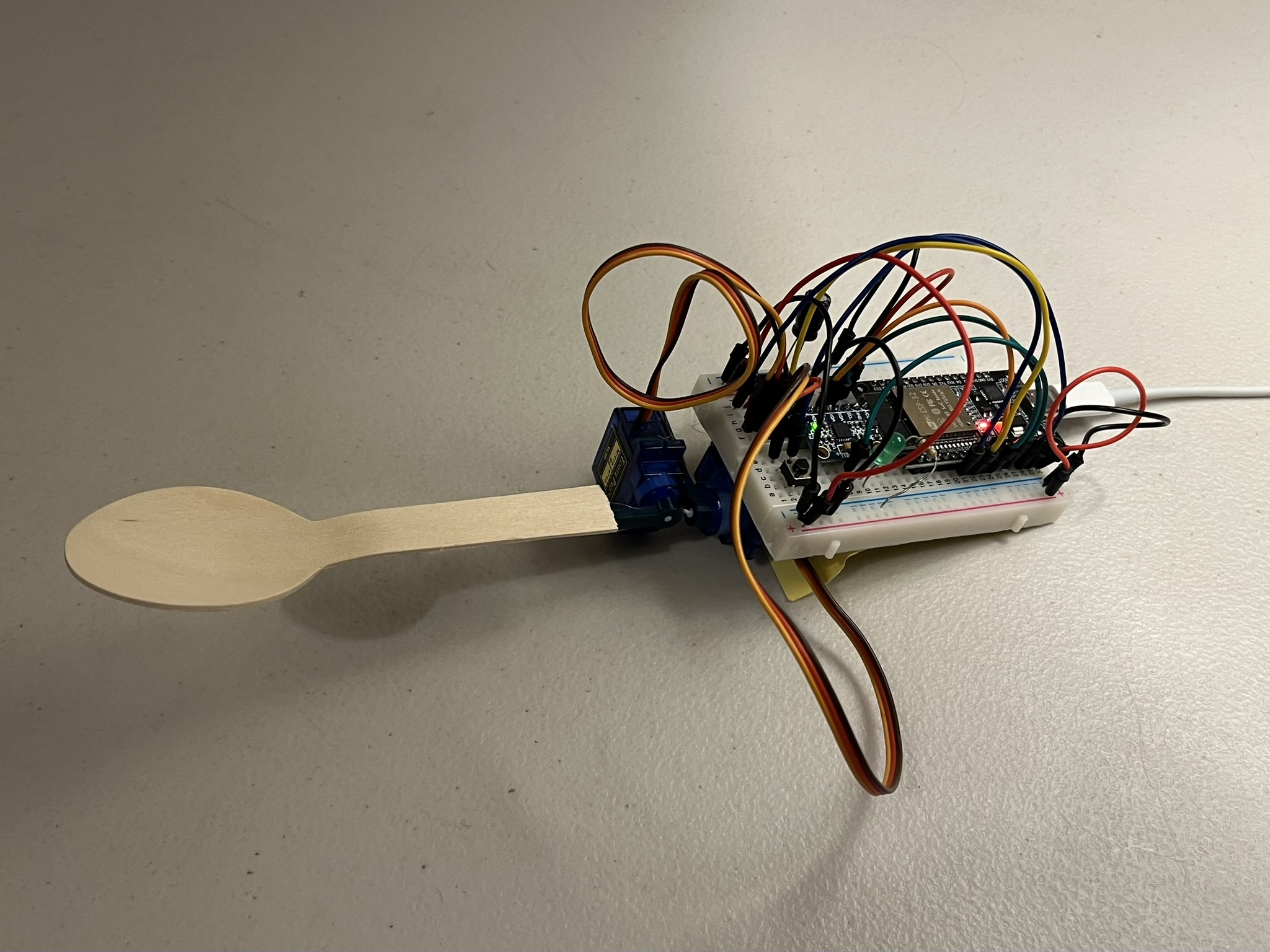
An ESP32-based self-levelling spoon that counteracts hand tremor (Parkinson’s / essential tremor) using IMU sensor fusion and two servos correcting roll and pitch in real time. Stabilising utensils already exist for this; this project isn’t a new invention, just an exercise in how quickly a working prototype could be built from parts already on hand. Prototype only, not a certified or clinically validated assistive device.
The ESP32 reads acceleration and angular rate from an MPU6050 over I2C and fuses them with a complementary filter to get a stable roll/pitch estimate that isn’t corrupted by either accelerometer vibration noise or gyro drift. Two servos, one per axis, are driven to counter whatever tilt is measured, holding the spoon head level while a button is held down. On boot, the filter zeroes itself against about a second of assumed-level readings, correcting for whatever angle the sensor happens to be mounted at.
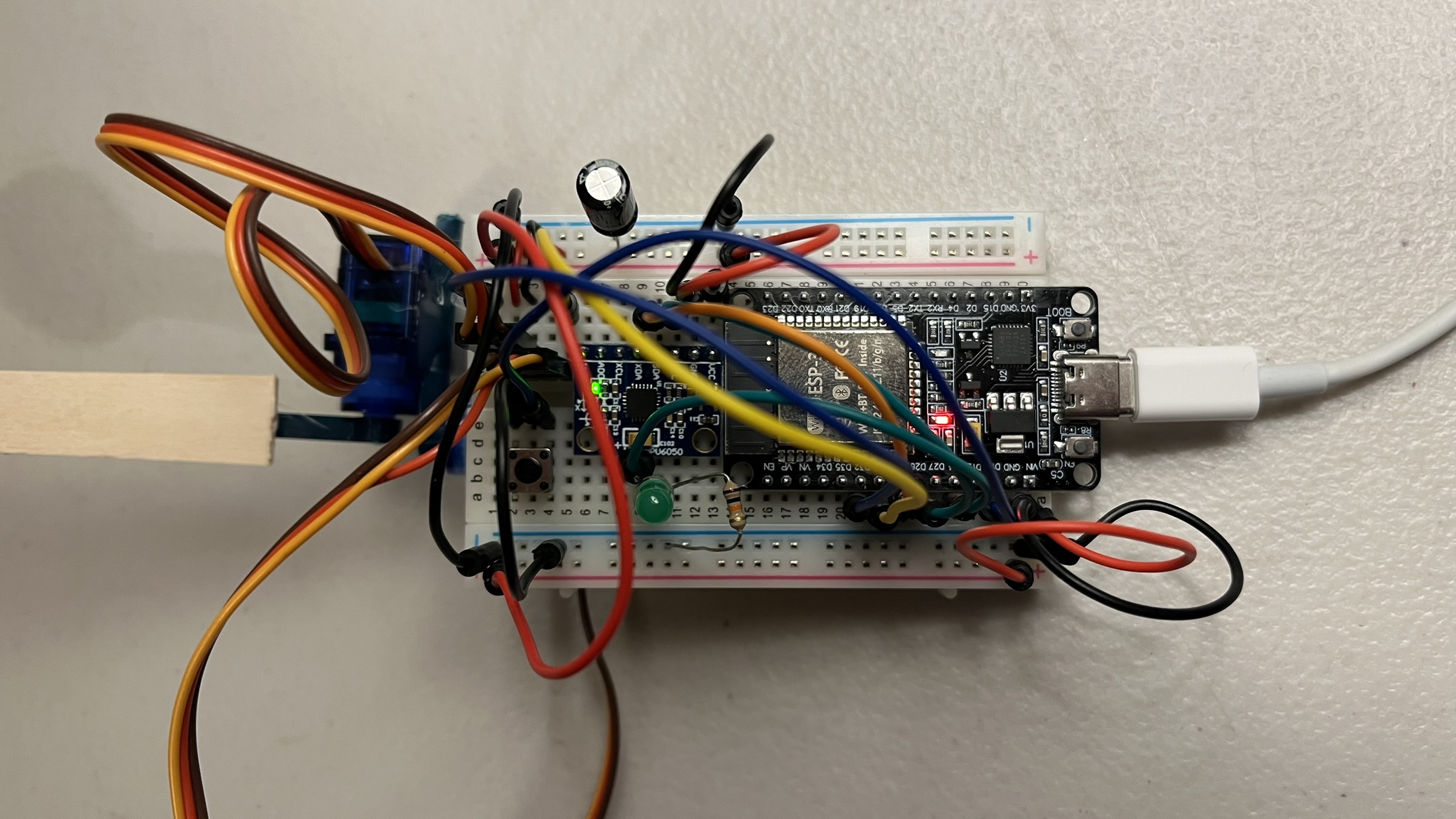
Hardware and wiring
| Part | Notes |
|---|---|
| ESP32 DOIT DevKit V1 | 30-pin, left-column pins used |
| MPU6050 breakout (GY-521) | I2C accelerometer + gyro, onboard regulator, powered from VIN |
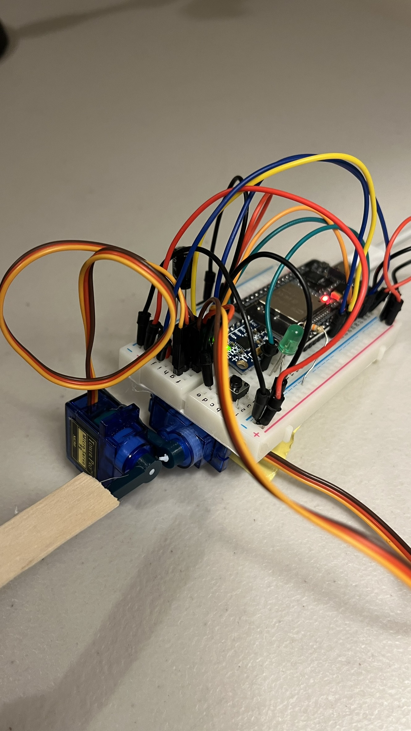
| Servo ×2 | MG90 metal-gear; SG90 plastic-gear is a drop-in substitute (same footprint/PWM/voltage, less durable under sustained cycling) |
| Pushbutton | Gates levelling on/off |
| LED + 220Ω resistor | Mirrors button state |
| Wooden spoon | Hot glued to the top servo horn |
| 470µF electrolytic capacitor | Bulk capacitor across the servo power rail |
| Function | GPIO |
|---|---|
| MPU6050 SDA | 25 |
| MPU6050 SCL | 26 |
| Servo 1 signal (roll) | 32 |
| Servo 2 signal (pitch) | 33 |
| Button | 13 |
| LED | 14 |
VIN (5V) feeds the MPU6050’s VCC and both servo red wires, with all grounds sharing one rail. The MPU6050 runs off VIN rather than 3.3V, since the GY-521 board carries its own onboard regulator tolerant of 3–5V input. A 470µF electrolytic capacitor sits across the servo power rail to absorb current spikes from the servos. D34/D35/VP/VN on this pin column are input-only and can’t drive a servo or LED, and D12 is a boot-strapping pin, deliberately left unused.
Firmware
Built on MPU6050 (Electronic Cats / jrowberg I2Cdevlib) for sensor access and ESP32Servo (Kevin Harrington) for servo PWM, since the standard Servo library doesn’t work reliably with the ESP32’s PWM peripheral.
Sensor fusion and levelling loop. Boot-time calibration averages 200 accelerometer samples (roughly one second), assuming the spoon starts level, and stores the result as a per-axis offset:
rollOffset  = atan2(ay, az) * 180.0 / PI;
pitchOffset = atan2(-ax, sqrt(ay * ay + az * az)) * 180.0 / PI;
Every loop iteration, a complementary filter blends the accelerometer’s absolute but noisy angle with the gyro’s integrated rate, which is smooth but drifts over time:
const float ALPHA = 0.98;
angleRoll  = ALPHA * (angleRoll  + gyroRollRate  * dt) + (1 - ALPHA) * accRoll;
anglePitch = ALPHA * (anglePitch + gyroPitchRate * dt) + (1 - ALPHA) * accPitch;
At ALPHA = 0.98, the filter trusts the integrated gyro for 98% of each update, so vibration on the accelerometer doesn’t reach the output, and leaks in 2% of the accelerometer’s reading each cycle to pull long-term drift back towards the true angle.
The corrected angle (filter output minus the boot-time offset) is constrained and applied against the servo’s centre position, so the servos actively counter whatever tilt is measured:
int rollCmd  = SERVO_CENTER - constrain((int)correctedRoll,  -SERVO_MAX_DEFLECTION, SERVO_MAX_DEFLECTION);
int pitchCmd = SERVO_CENTER + constrain((int)correctedPitch, -SERVO_MAX_DEFLECTION, SERVO_MAX_DEFLECTION);
This only runs while the button is held; releasing it returns both servos to centre and turns the LED off.
Limitations
MG90/SG90 servos have a slew rate of roughly 60° per 0.1s. Essential tremor runs at roughly 4–12 Hz and Parkinsonian tremor at roughly 4–6 Hz, so at the faster end the servos likely can’t fully track the tremor itself — this validates the sensing and control loop rather than proving clinical-grade tremor cancellation. The ESP32 and both servos also share one 5V rail: the bulk capacitor across the servo supply mitigates brownout resets from servo current spikes, but separate regulation would still be needed before running off a battery.
Controls: hold the button to activate levelling (LED lights up); release it and both servos return to centre (LED off).
Stack: ESP32 (Arduino), MPU6050, ESP32Servo
Status: complete (prototype)