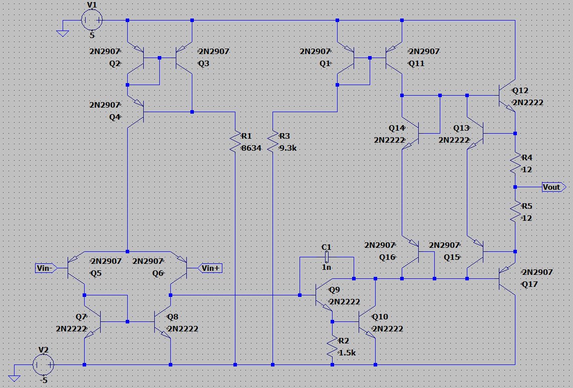
Op-amps are the workhorse of analogue electronics and learnt about what actually going on inside, so over a few months of teaching myself the theory I built one from individual transistors in LTSpice instead.
An op-amp has to amplify the difference between two inputs while ignoring anything common to both, then supply enough current to drive a real load. That splits into a few distinct jobs, and I learned each one as its own stage before wiring them together:
Differential pair: two transistors sharing a tail current, taking the two inputs and turning their difference into a single signal. This is the front end that gives an op-amp its defining behaviour.
Current mirrors: matched transistor pairs, used in place of plain resistors to set the diff pair’s tail current and to act as its load. A current-mirror load gives far more gain than a resistor would, which is most of where the op-amp’s overall gain actually comes from.
Push-pull power stage: the final stage, the one that delivers real current into a load rather than voltage into a probe. A single transistor can only push current one way, so it splits into complementary NPN and PNP halves, each with its own mirror predriver, so the output can swing a real load through 0V in both directions.

The finished circuit runs to seventeen transistors: 2N2907 PNPs for the input differential pair, the upper current mirrors, and the PNP half of the push-pull output; 2N2222 NPNs for the tail source, the second gain stage, and the NPN half of the push-pull output. It’s biased off a split ±5V supply rather than a single rail, which is what lets the output swing through 0V like a real op-amp instead of sitting offset. R1 and R3 (8.6kΩ and 9.3kΩ) set the mirror currents that establish the open-loop gain, a 1nF cap across the second stage keeps it from oscillating once the feedback loop closes, and a 12Ω resistor on each output transistor limits the current the push-pull pair can dump into a short.
Checking the gain
To prove the finished amplifier actually behaved like an op-amp, I built a simple test bench: the amplifier wired as an inverting stage, input resistor fixed at 1kΩ, and the feedback resistor stepped through 1k, 10k, 100k, and 1M across the same AC sweep.
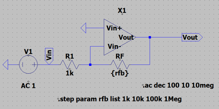
For an inverting amplifier the textbook gain is just the resistor ratio, Rf/Rin, so each feedback value has a clear number to check against: 1k should give ×1 (0 dB), 10k should give ×10 (20 dB), 100k should give ×100 (40 dB), and 1M should give ×1000 (60 dB). Reading the flat, low-frequency part of each curve off the plot and converting it back from dB to a linear value lined up with those predictions almost exactly. Only the 1M case came in a touch low, around 59 dB instead of 60, which is the amplifier’s own finite open-loop gain starting to limit how much closed-loop gain it can actually deliver.
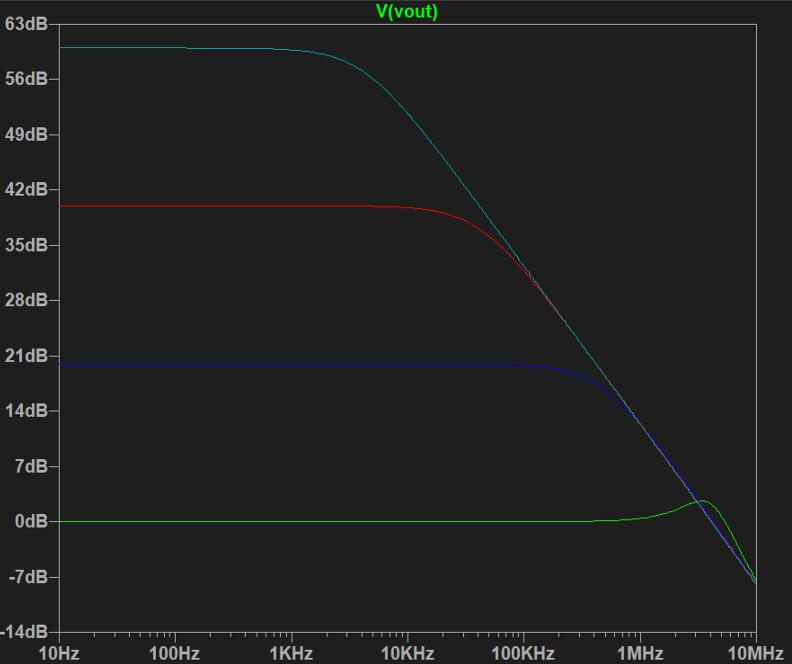
The same plot shows the usual gain-bandwidth trade-off too: the higher the feedback resistor pushes the gain, the earlier it rolls off, since gain and bandwidth are linked by the same finite gain-bandwidth product in any real amplifier, discrete or otherwise.
Stack: LTSpice
Status: complete