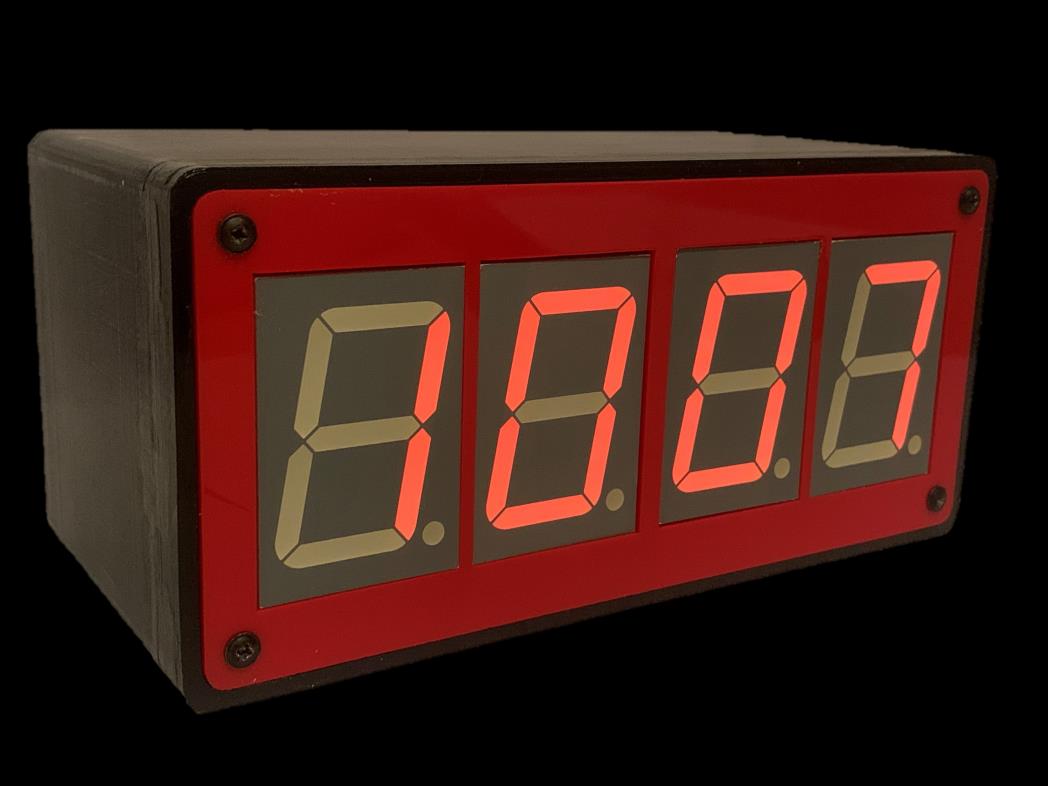
A 24-hour digital alarm clock, designed and built from scratch for a real client brief, from research and spec through to a finished, tested product.
The brief: my client needed a desk clock to get him to meetings on time. Accurate, easy to set, readable from across the room, and able to run off mains or battery. That became a spec: under £30, under 1kg, accurate to a minute a week, visible and audible from 3m, two-tone colour scheme.
Research: client interviews, a group questionnaire, a mood board, and anthropometric sizing for the buttons and case. I also tore down a few commercial products for ideas: a Dyson vacuum’s bold two-tone colour and no-exposed-parts design ethos, a cheap analogue clock’s night light and alarm, and Fitbit’s legible interfaces. That fed a red-and-black two-tone scheme, filleted edges for grip, and a fully enclosed case.
Timekeeping: rather than trust the microcontroller’s own clock, a 32.768kHz crystal (X2) feeds a 4060B ripple counter (IC6) to divide down to an exact 1Hz pulse. A Genie 20 microcontroller (IC7) counts those pulses to track time, drives all four seven-segment displays through four 4026B decade counters (IC1-IC4), and stores the time and alarm in EEPROM so both survive a power cut. Six buttons feed the Genie directly: clock set, alarm set, increment, 12/24hr switch, confirm/stop alarm, and reset, alongside the volume pot (VR1) and buzzer (BZ1) on the alarm output.
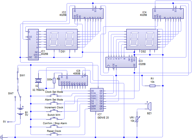
Electronics: three iterations. First, a 555 timer flashing an LED once a second, nowhere near accurate enough. Second, the Genie and seven-segment displays, but the time lived in main memory and was lost on every power cut. Third fixed both: the crystal-and-4060B timebase for accuracy, EEPROM for persistence, a distinct alarm-setting mode, and a battery/mains toggle.
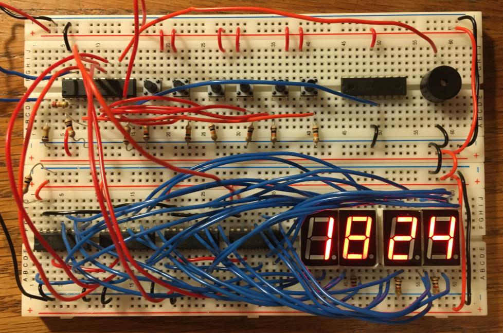
I proved the full circuit on breadboard first: all four displays, the button matrix, and the buzzer running off the real logic, so problems showed up while still easy to rewire.
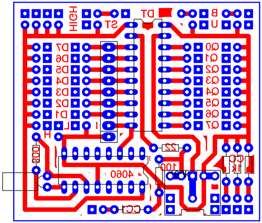
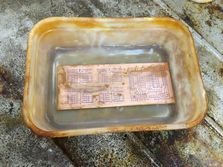
Once proven, I laid it out as a custom single-sided PCB and etched it by hand: printing the design onto acetate, exposing a copper-clad board under UV light, developing it, then etching the copper in a heated tank before drilling every hole.
Partway through assembly, the seven-segment displays turned out to need more current than the logic ICs could tolerate at 5V, so I added a second small board: an LM7805 regulator and smoothing capacitor stepping 9V down to a clean 5V, so the whole circuit could still run off one battery.
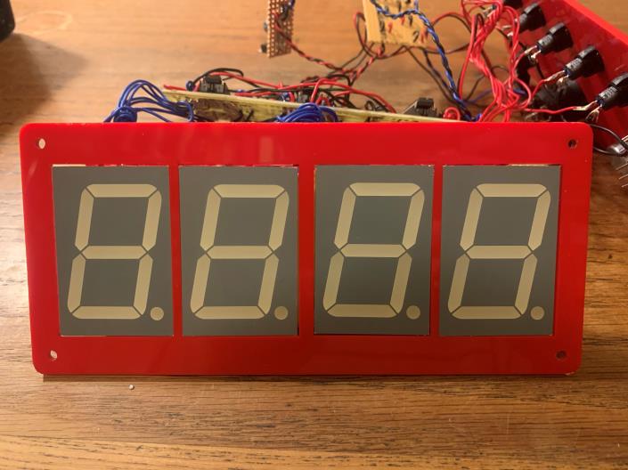
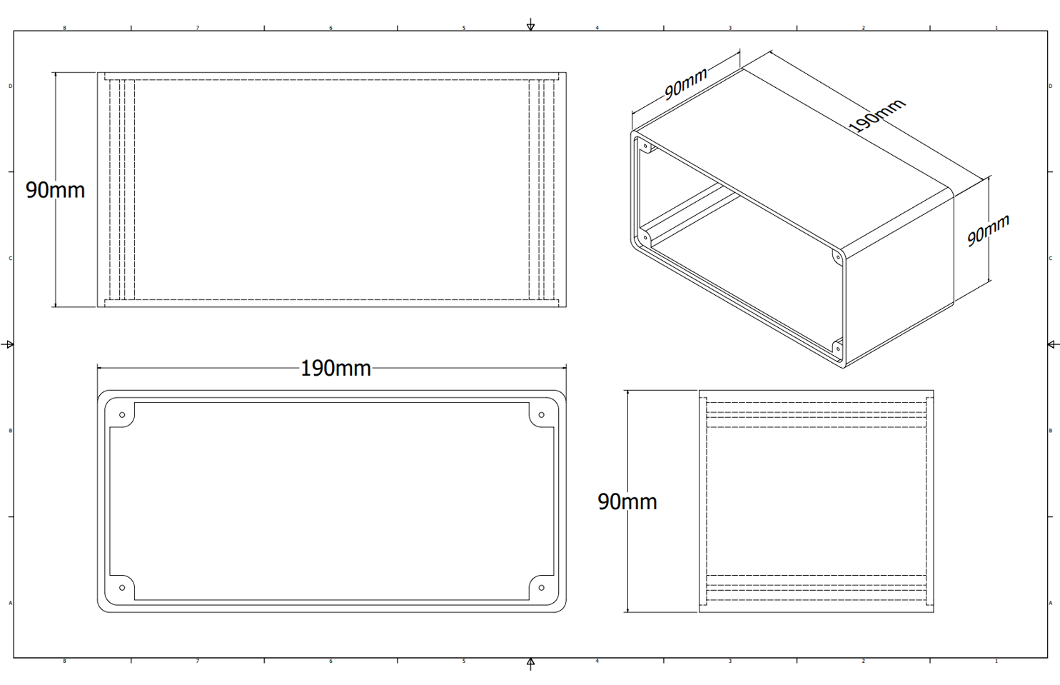
Case: a 3D-printed PLA base (CAD’d in Autodesk Inventor, filleted edges for grip) with laser-cut acrylic front and back faces, sprayed with UV-resistant paint. Both faces are removable for battery access and debugging.
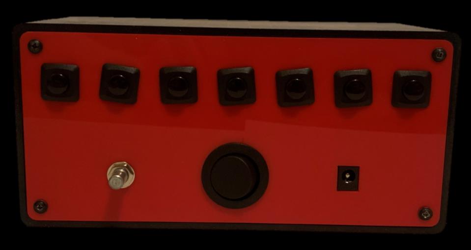
Controls: seven buttons on the back for clock/alarm setting and a test-buzzer button, a variable resistor for alarm volume, and a mains/battery power switch.
Testing: every spec point got measured. 190×90×90mm and 500g, both well inside the limits. Accurate to within a minute over a week with no adjustment. Legible and audible from 3.5m. A focus group changed the battery in 68–93 seconds each, under the 2-minute target.
What I’d change: label the back-face buttons, add a logo to the bare side panels, and fix a colour mismatch between the display bezels and case. All feedback from the client and focus group. I also looked at injection moulding as a cheaper-per-unit alternative for a hypothetical production run, at the cost of a much higher tooling setup.
Stack: Digital logic (Genie microcontroller), PCB design and etching, Autodesk Inventor (CAD), 3D printing, laser cutting
Status: complete
Full documentation: complete design folder (PDF, 53 pages): research, client interviews, circuit iterations, PCB manufacture diary, and evaluation against every specification point.