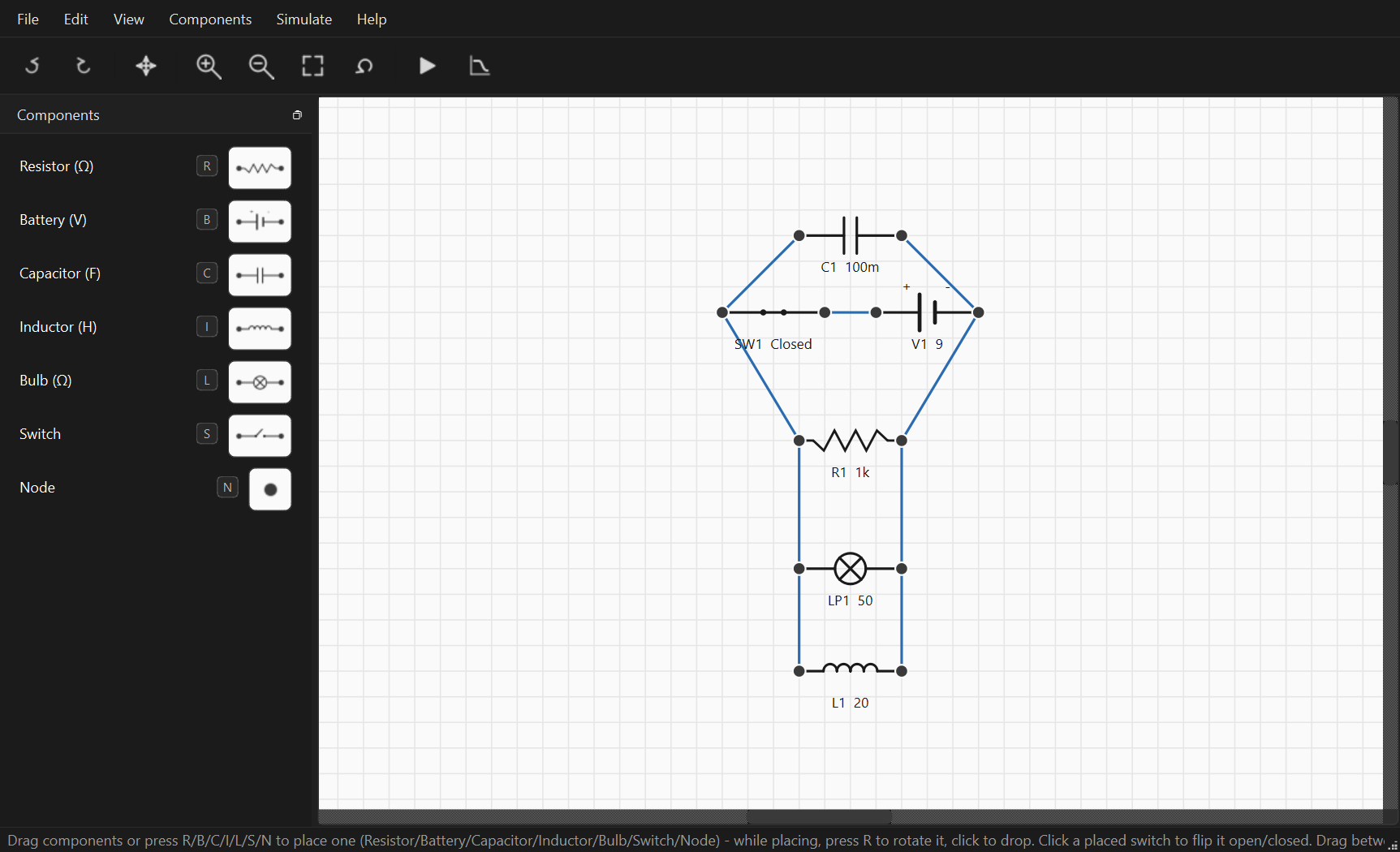
A desktop app for sketching circuit schematics and simulating them, built with Python and PySide6 (Qt). Drop components onto a canvas, wire them up, and either watch the voltages settle live or sweep a frequency response.
Components (resistor, battery, capacitor, inductor, bulb, switch, and a bare node) go down with a shortcut key or a sidebar click, into a placement mode where a ghost follows the cursor until you click to drop it. Wiring is drag-between-terminals; dropping a wire on an existing one taps into it, and landing both terminals on the same wire splices a component in directly. Everything goes through undo/redo, including renames and revalues.
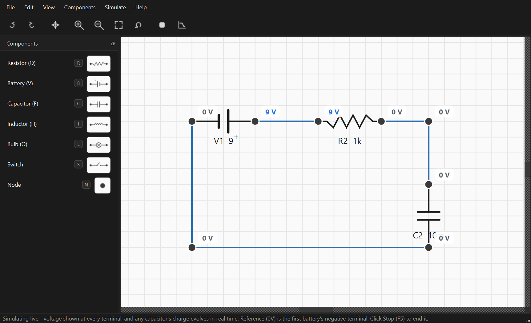
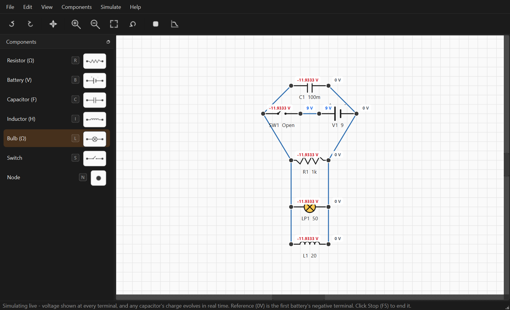
Simulate (F5) runs a live DC solve and labels every terminal’s voltage as you edit. Capacitors and inductors charge and discharge over real time rather than snapping to steady state, so opening a switch after current has built up in an inductor makes the whole network swing negative for a moment as the kickback plays out.
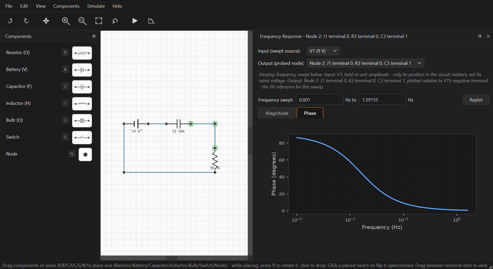
Frequency Response opens a Bode plot panel where you pick the driving source and probe node and flip between magnitude and phase. The sweep range is guessed automatically from the circuit’s own component values, and the panel spells out what’s being varied and what the plotted values are relative to.
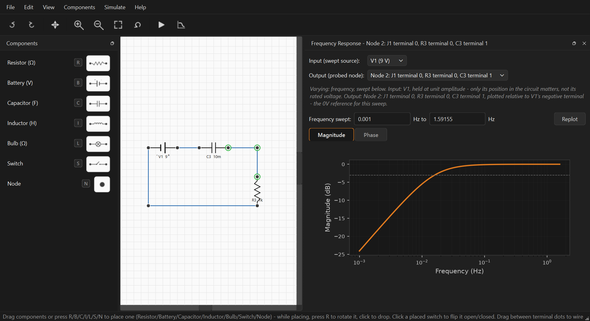
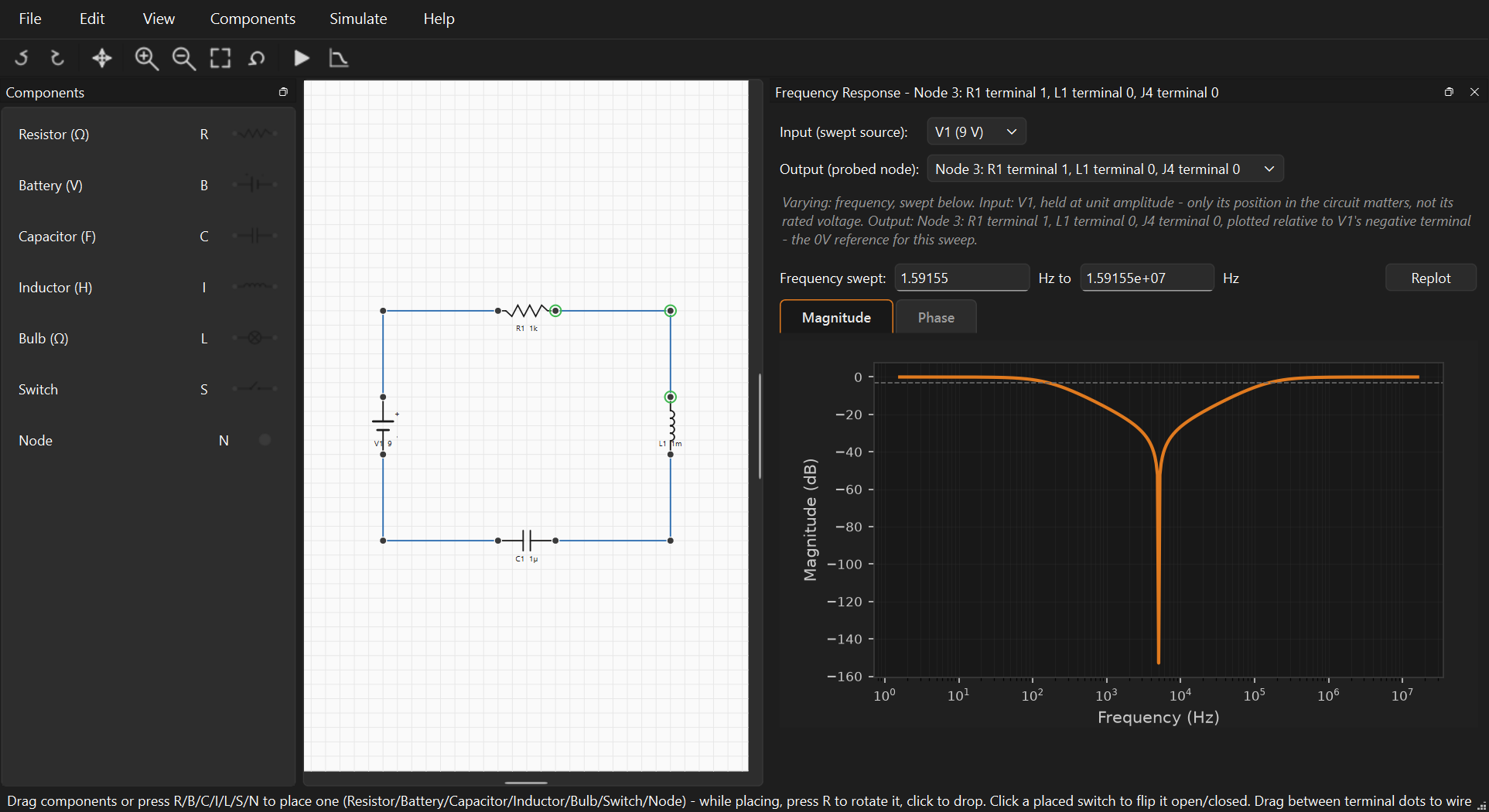
The same panel works just as well on a series RLC circuit, though the result looks nothing like the highpass roll-off above. With the resistor, inductor, and capacitor all in series, the two reactances cancel out exactly at the resonant frequency, so the voltage measured between them collapses to almost nothing right at resonance instead of peaking there. The result is a sharp notch, not a bump, dropping over 140dB before recovering on either side.
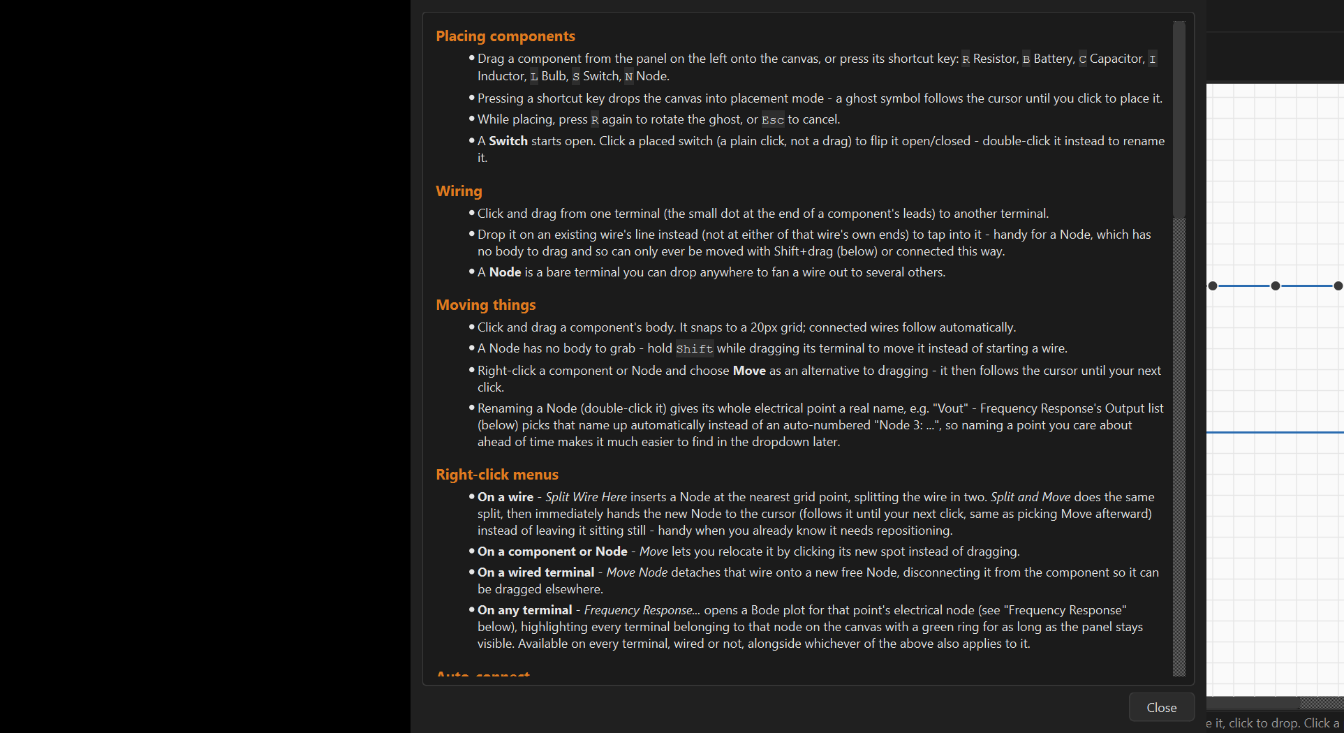
Save/open is plain JSON, and a handful of worked examples ship in example_files/ (RC and RLC circuits, a voltage divider, parallel resistors, and a few basics circuits), so the app doesn’t open onto an empty canvas. There’s also zoom/pan and a full shortcut reference under Help > Controls (F1).
Underneath the UI, core/ is deliberately Qt-free: circuit_model.py holds the plain-data circuit representation and JSON save/load, simulation.py does DC and transient nodal analysis, and ac_simulation.py generalises it to complex-valued nodal analysis for AC: resistors as a real admittance, capacitors as jwC, inductors as 1/(jwL). No NumPy or SciPy; the linear algebra is hand-written using Python’s own cmath.
Testing: a large set of standalone assertion scripts rather than a pytest suite, covering the solvers, wire splitting/tapping, undo/redo, and UI interactions, runnable together or individually.
What’s next: a proper ground symbol (0V currently defaults to the first battery’s negative terminal), current readouts, multi-select with copy/paste, right-angle wire routing, and a packaged executable.
Controls: place a component with its shortcut key or sidebar, drag between terminals to wire, F5 to simulate, F1 for the shortcut reference.
Stack: Python, PySide6 (Qt), Matplotlib
Status: in progress