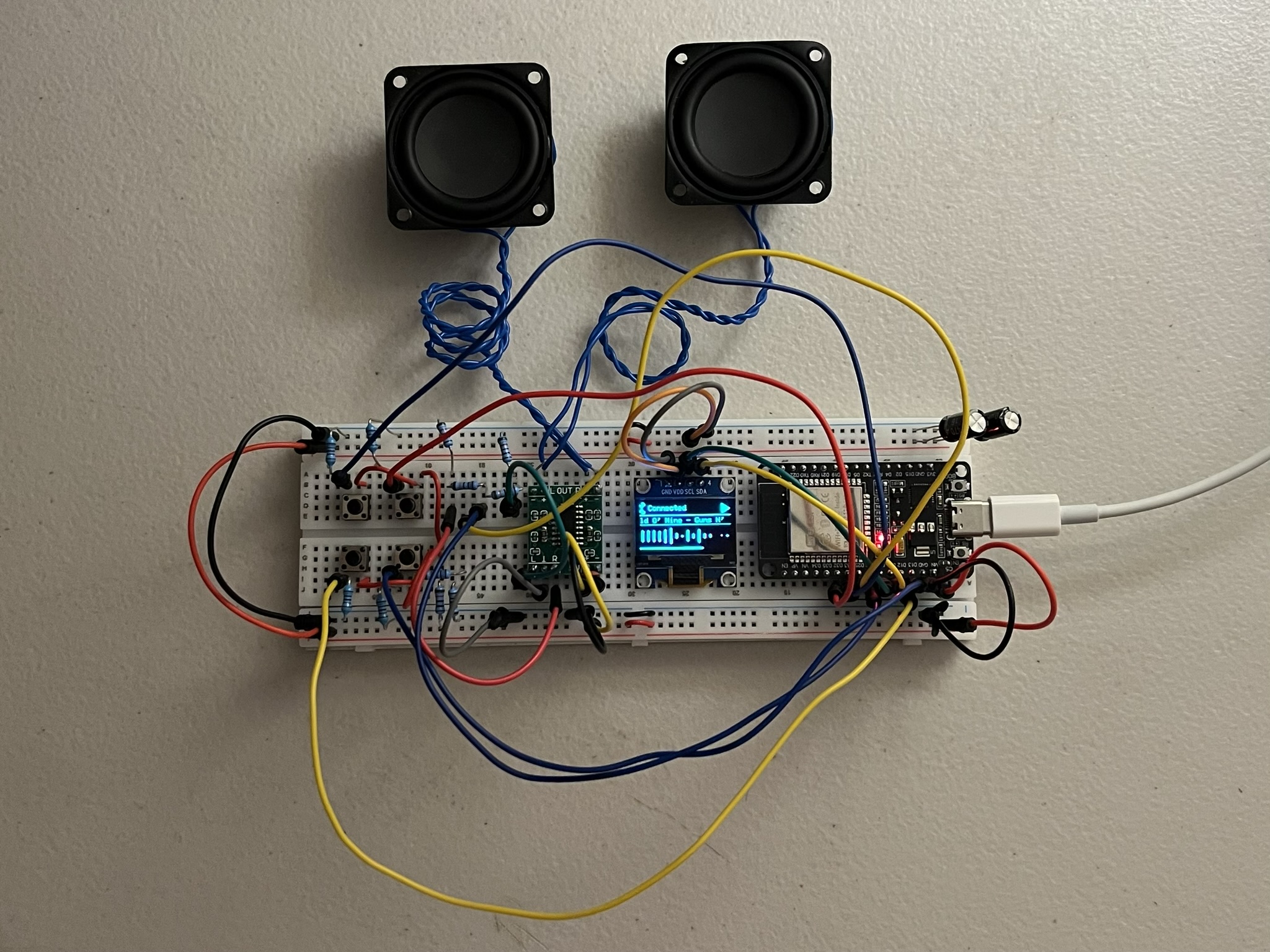
An ESP32-based Bluetooth speaker with an OLED status display and a live FFT spectrum analyser. The ESP32 receives audio over Bluetooth (A2DP) and pushes it out through its internal DAC into a resistor-divider stage and a PAM8403 class-D amplifier driving two speakers, while the OLED shows connection state, playback status, scrolling track metadata, and a 16-band spectrum driven directly off the audio.
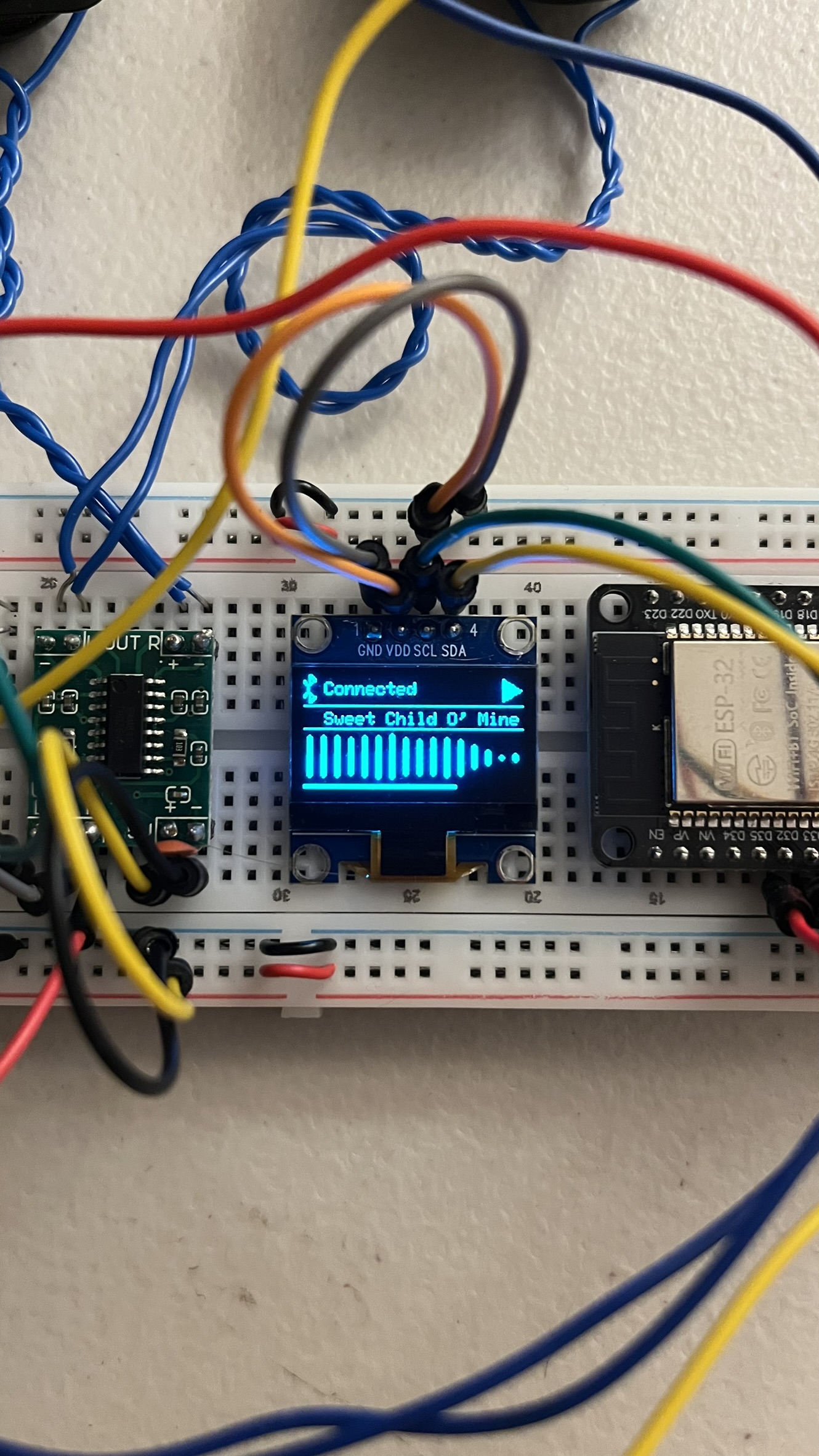
Hardware and wiring
| Part | Notes |
|---|---|
| ESP32 dev board | Left-column pins only; not seated in the breadboard, connected via jumpers |
| SSD1306 OLED | 128×64, I2C |
| PAM8403 module | Pre-built, onboard passives already present |
| Speaker ×2 | 5W/4Ω each |
| Pushbuttons ×4 | Pull-down config |
| Bulk cap | 940µF electrolytic, across VIN/GND |
| Resistor divider ×2 | 10kΩ+10kΩ, one per channel, between DAC pin and amp input |
| Function | GPIO |
|---|---|
| I2C SDA (OLED) | 14 |
| I2C SCL (OLED) | 27 |
| DAC Left | 25 |
| DAC Right | 26 |
| Volume up | 32 |
| Volume down | 33 |
| Play/pause | 12 |
| Mode (BT/AM, unimplemented) | 13 |
The DAC feeds each channel’s 10k+10k divider, whose midpoint goes into the PAM8403’s L/R input pads: the divider both prevents clipping and stops the input floating when nothing’s playing. PAM8403 ground, ESP32 ground, and every button’s pull-down all share one common rail. The amp’s outputs are BTL (differential, bridge-tied load), so neither speaker terminal is a true ground; each speaker only ever connects across its own matched +/− pair, not to the shared rail.
Firmware
Built on BluetoothA2DPSink (A2DP + AVRCP) with AnalogAudioStream driving the internal DAC. Connection-state, play-status, and track-metadata callbacks feed the OLED directly; volume and play/pause are debounced and functional, while the mode button is wired but currently a no-op, reserved for switching to a planned AM radio front end that isn’t built yet.
The FFT spectrum analyser
This is the most involved part of the firmware, and runs in three stages: capture, transform, and banding.
Capturing samples without blocking audio. set_stream_reader() hands the raw Bluetooth PCM stream to read_data_stream(), which runs on the Bluetooth stack’s own task, not loop(), alongside normal playback. It has to be fast and non-blocking or it stalls audio, so it just strides through the interleaved stereo stream, grabs the left channel, and fills a ring buffer:
volatile bool fftBufferReady = false;
int fftWriteIndex = 0;
int16_t fftCaptureBuffer[FFT_SAMPLES];

void read_data_stream(const uint8_t *data, uint32_t length) {
  if (fftBufferReady) return; // loop() hasn't consumed the last buffer yet — skip this packet
  int16_t *samples = (int16_t *)data;
  uint32_t sampleCount = length / 2; // 16-bit samples
  for (uint32_t i = 0; i < sampleCount && !fftBufferReady; i += 2) {
    fftCaptureBuffer[fftWriteIndex++] = samples[i];
    if (fftWriteIndex >= FFT_SAMPLES) {
      fftWriteIndex = 0;
      fftBufferReady = true;
    }
  }
}
Two tasks, the Bluetooth stack and loop(), share fftCaptureBuffer with no mutex protecting it. That’s safe here specifically because the fftBufferReady flag enforces strict turn-taking: the writer stops the instant the buffer fills, and only starts again once the reader clears the flag. A real mutex would be overkill, and riskier too, since blocking the Bluetooth task risks audio glitches, for a producer/consumer pair that by design never touches the buffer at the same moment.
Turning samples into a spectrum. Once a buffer’s ready, loop() removes the DC bias (subtracts the mean, so a nonzero average sample doesn’t show up as a fake low-frequency spike), applies a Hamming window (tapers the block’s edges so the FFT doesn’t misread the sudden cutoff as extra frequency content), then runs arduinoFFT:
double mean = 0;
for (int i = 0; i < FFT_SAMPLES; i++) mean += fftCaptureBuffer[i];
mean /= FFT_SAMPLES;
for (int i = 0; i < FFT_SAMPLES; i++) {
  vReal[i] = (double)fftCaptureBuffer[i] - mean;
  vImag[i] = 0.0;
}
fftBufferReady = false; // release the buffer back to the audio callback

FFT.windowing(FFTWindow::Hamming, FFTDirection::Forward);
FFT.compute(FFTDirection::Forward);
FFT.complexToMagnitude();
With 256 samples at a 44.1kHz sample rate, that gives 128 usable frequency bins spaced linearly from 0Hz to roughly 22kHz.
Bins to bars. 128 linear bins don’t map well onto 16 bars: most bins fall in the treble, and bass gets squeezed into one or two. computeBands() groups bins logarithmically instead, so each bar spans roughly one octave, matching how pitch is actually perceived:
int startBin = minBin + (int)pow((float)usableBins, (float)band / NUM_BANDS);
int endBin   = minBin + (int)pow((float)usableBins, (float)(band + 1) / NUM_BANDS);
Each band also tracks its own recent loudest and quietest level in dB, snapping instantly to a new extreme and easing back slowly otherwise:
if (db > bandCeilDb[band]) {
  bandCeilDb[band] = db;             // new loudest moment: snap up now
} else {
  bandCeilDb[band] -= RANGE_RELEASE; // otherwise ease back down
}
if (db < bandFloorDb[band]) {
  bandFloorDb[band] = db;            // new quietest moment: snap down now
} else {
  bandFloorDb[band] += RANGE_RELEASE; // otherwise ease back up
}
The current reading is then normalised into that floor-to-ceiling window. That’s what keeps quiet songs showing visible bar movement instead of flatlining, and stops loud songs just pegging every bar at max: the scale continuously adapts to whatever’s actually playing instead of using one fixed dB range for all music.
What’s next: swapping the internal 8-bit DAC for an external I2S DAC (a PCM5102) for cleaner audio and to free GPIO26 from being DAC-locked; finishing the AM radio front end, a hand-wound ferrite loopstick, variable capacitor, and 1N34A germanium diode feeding into the PAM8403, as the second source; adding proper switching hardware (an analogue switch IC or relay) so the mode button can actually flip between Bluetooth and AM; moving the AM section onto its own breadboard, since RF pickup is sensitive to noise from the ESP32 and amp; and moving off USB-C power onto a dedicated 5V rail so the amp isn’t sharing power with the microcontroller.
Controls: two buttons for volume, one for play/pause, and a fourth reserved for switching to the AM source once that hardware exists.
Stack: ESP32 (Arduino), ESP32-A2DP + arduino-audio-tools (pschatzmann), Adafruit SSD1306 + GFX, arduinoFFT (kosme)
Status: in progress — Bluetooth playback, amp stage, and the FFT display all working; AM radio source still to come